
How is the terminal held?
The fixture must retain the terminal while the opposing grip holds the free wire. Send a front and side view of the crimped assembly so the engineer can review the contact surfaces and pulling direction.

Will the holder fit my terminal?
For a ring terminal, send the inside diameter of the hole and the clearance behind the barrel. For a fork or blade terminal, mark the edge the holder can bear against. Include a photo along the wire axis and another from the side. These views help us check whether the terminal will sit straight under load.
In the quotation, ask us to identify the terminal holder, wire grip, fitted load cell and working force range separately. If you need a peak reading, a hold test or an exported result, include that requirement with your sample.
See the fixture and sample guide · Request a fixture review for this tester
Specify the wire and pull force
Include the conductor cross-section in mm² or AWG and the expected force, or minimum required pull force, in N, kN or lbf. Share the terminal form and any insulation or wire preparation requirements.
Identify the test method
Give the standard number, revision and any customer-specific acceptance criterion. Different test methods may specify different specimen preparation, grip geometry or pull speed.
What to send for a crimp pull test quote
Provide the terminal type and dimensions, a front and side view, the conductor cross-section in mm² or AWG, and the expected or minimum pull force with units. If the force is unknown, share a sample drawing or photo. Include the standard number and revision or your customer specification, plus any pull speed and insulation preparation requirements.
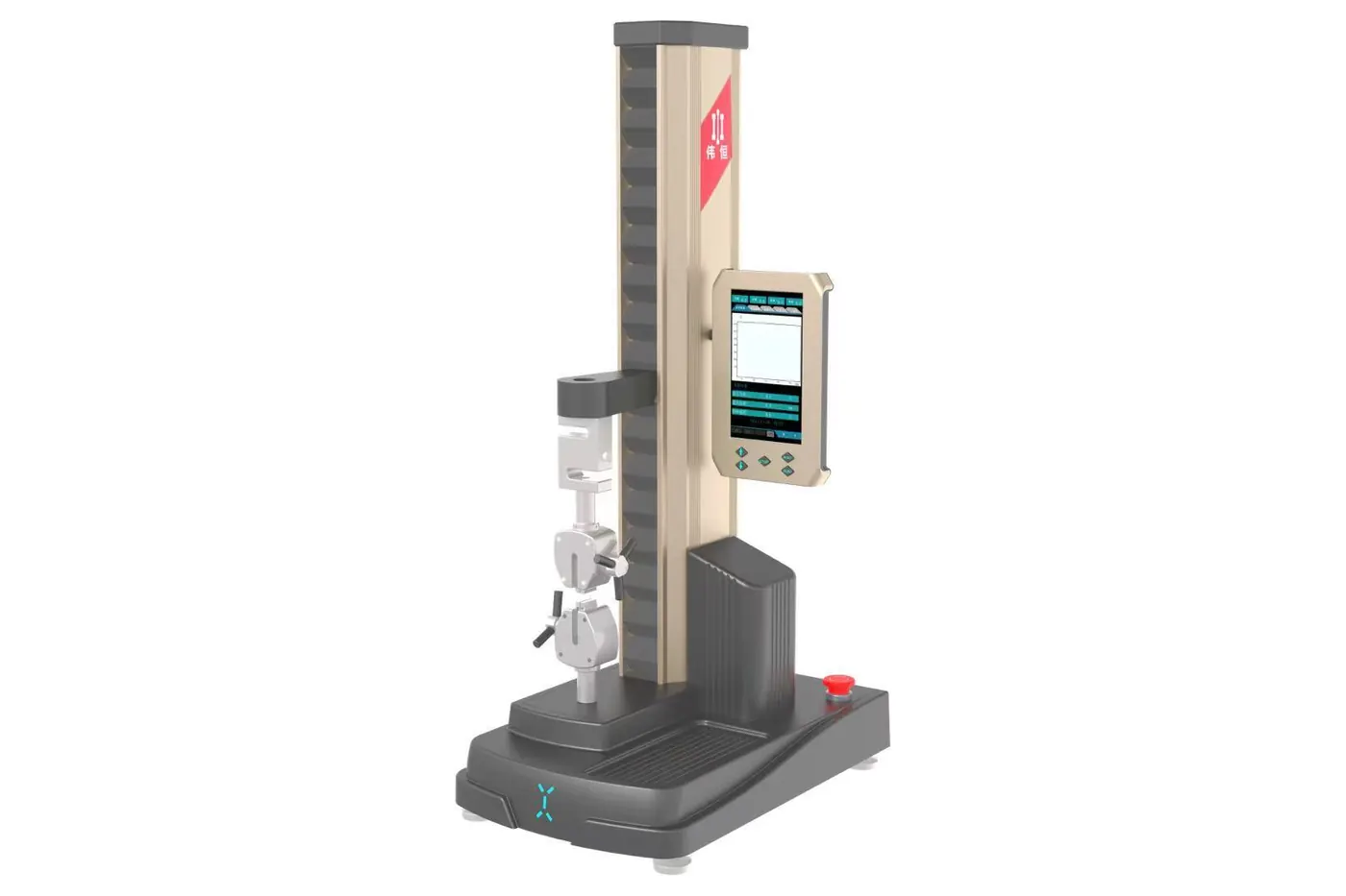
We use those details to review the terminal holder, opposing wire grip and force range. A configuration illustration for the WH-8283 benchtop tester shows the frame and controller. The terminal fixture is selected separately.
See the terminal and wire fixture selection guide
Selecting the terminal holder and wire grip
The illustration shows a benchtop PC arrangement as a frame reference. The terminal holder and wire grip are selected for the connection being tested. A front and side photo helps us identify the retaining surface.
Benchtop frame reference

What to send for a quotation
Send front and side views of the terminal, wire size in mm² or AWG, expected pull-off force (N or lbf), and the test standard and revision. If the acceptance force is unknown, share the customer drawing or test specification.